|

1551 S. Harris Court, Anaheim, CA 92806 Anaheim, CA 92806
Phone: 714.978.1551  Fax: 714.978.0431 Fax: 714.978.0431
Model 3500E Series, Automatic, Gantry, Large Area, Wedge Bonders Last revised 11/08/2005
Overview
Model 3500E is a gantry with overhead ways and a moving bond head that brings the bonding function to the work and leaves the material handling process flow under customer control. It uses the full 2400B Series software to locate and bond automatically fine wire connections arrayed over a large, stationary work piece. There is no limit to the size of the work as this machine is entirely above the bond plane. The area traversed for bonding is five and three-eighths by nine and one-half inches; and successive areas could be presented.
The wedge-wedge bonding method accepts aluminum wire, or gold wire with work piece heat. The primary wire feed method through angled clamps can be converted by exchange of clamp assemblies to vertical-feed wedge bonding for deep-walled work packages. This machine is intended to bond groups of parallel wires on work pieces pre-aligned for front-to-back bonding. Quality expectation is high with missing wire detection that functions without work contact, and with on-screen presentation of bond progress via a second, side-view camera.
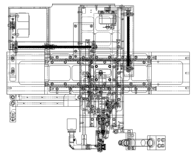
Bonding proceeds along a programmed path to all targets across the bond area; locating each target by Pattern Recognition and correcting for placement error. Programming of the work path makes use of the fully developed and richly featured software from West Bond’s Model 2400B running under Windows. Interface is by keypad, mouse, and large LCD color display.
Mechanical
Tool transport mechanism is constructed of three axes, straight-line and orthogonal, all driven by stepper motors in micro-step mode under program control. The long "X" and "Y" axes are moved via lead screw, and the "Z", by a linear spiral cam. A fourth motor drives the Patten Recognition camera assembly in "Z" direction for focus; and a fifth, sets force for each bond by varying the initial compression of a force counterbalance spring. A sixth motor is programmed to move either angled or vertical wire feed-clamps about the forward pivot to terminate and feed wire. The transducer and clamp assembly is mounted on a four-bar linkage that does not bear the weight of any motor. Wire is drawn from a spool by the clamps and is fed to underlie the tool bond-foot.
All movement ways are hardened and ground vees with crossed rollers. The lead screws are positioned outside the ways, so to be accessed for maintenance without disassembly Fine accuracy is assured by closed-loop feedback to the motor controls from an optical encoder system with glass scales and laser sensors mounted within the X- and Y-Axes.
Ranges, Ratios and Resolutions
|
Bond "Y" |
Range |
5.375 inches (plus offset) |
|
|
Resolution |
0.0001 inch per encoder division |
|
Bond "X" |
Range |
9.500 inches |
|
|
Resolution |
0.0001 inch per encoder division |
|
Bond "Z" |
Range |
0.500 inch |
|
|
Resolution |
0.0001 inch per motor micro-step |
|
Offset "Y" |
Distance |
0.625 inch, making total "Y" range, 6.0 inches. |
Bond Tool Head Assembly 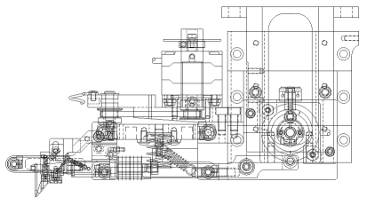
The new forward-pivot tool assembly of this series is built around K~Sine Transducer, Model No. 24-W, operated at 63 KHz. The transducer and wire clamps depend from the "Z" axis slide by a four-bar linkage to keep the tool vertical and extendable to any position that tunes ultrasonically, and to reduce mass on the bond. Bond tools for both angled- and vertical-feed configurations are 0.750" length, dropped 0.656" below center. Vertical clearance is a full 0.391" everywhere under this tool head and all other mechanism except for wire presentation at 45 ° for angled-feed.
Actuation of all clamp motion is through a follower on the four-bar mechanism that rides on a motor driven cam mounted independently. Appropriate clamp motion settings for each method are configured in software and are retained in non-volatile memory. Motions toward the tool are spring-driven, while the more powerful motor drives away from the tool – to ease concerns during set-up.
Wire Clamps are air-opened and spring-closed, and have self-contained closure pivots. A separate pivot about an axis located to serve both overhead and angled-feed generates the clamp motions along their lines of feed action. To change between angled-feed and vertical-feed, it is necessary only to exchange the small clamp assemblies and to change the wire drag means. Alignment of clamps to the tool is facilitated by individual adjustments along three axes.
Rigid bearing mounts, rather than taper loading, fix the strut bar of this assembly so that any required bond force can be applied. Bond Force is set to program values by a motor with spiral cam that adjusts the initial compression of the force spring. This force is opposed by a constant spring that serves to hold closed firing switch contacts until bond contact. Radiant tool heat with panel mounted, constant current control is included.
Machine Configuration
The mechanism of this series was designed to mount above a customer's work handling system, to be confined entirely above the work plane, and so not to require any base or work platform: Custom mounting brackets can be designed to join to customer’s mechanism. This configuration is designated by the appended "X", as Model 3536EX. For tabletop application, the standard model of this Series, Model 3536E, is without any work holder or temperature controller. The floor-standing configuration becomes Model 3536E-90 by the addition of Feature –90, Frame. In any configuration, the Industrial Computer CPU Chassis and West·Bond’s Power Supply Chassis are housed as separate components.
A motorized Wire De-spooler, Assy No 10065, for 2-inch spools, and which also includes side-view Television Camera Assy No 10110 with Polaris Model No. MB-1250 Camera, is mounted on the Y-Axis.
A unique utility to detect bond fault is included, so to halt immediately to prevent damage to subsequent bond sites.
ESD protected Olympus Model SZ51-60 Microscope with 15X eyepieces and the new LED illuminator "Luxuray" are included. No other microscope has equivalent clearance to the bond head. This microscope is mounted on a folded linkage that allows it to be positioned to view most of the bond area.
Electrical Software and Hardware
A software control program, well developed and in long use for West Bond Model No. 2400B, is adapted to serve this model as well. This program runs under Windows XP Professional and is executed by a Pentium 4 processor housed in an Industrial CPU enclosure. Pattern Recognition is accomplished by Matrox components. The User Interface is displayed on a large LCD color display, and consists of many screen forms for user interaction. This display also presents embedded views from two separate cameras, a vertical view of the work piece during alignment, and an angled view of progress during bonding. Input controls require a mouse, a keypad and a control-switch pad. User data of machine configuration, and of device targets and image patterns, can be saved to 128MB (or greater) USB Drives, Hard disk, or Floppy disk.
The separate power supply enclosure holds motor and logic electrical power supplies, and also K~Sine Part No 6795, four Watts, dual channel ultrasonic power supply. Settings of power and time program values are sent via an eight-bit interface.
ESD Protection
Protection against Electrostatic Discharge is implemented by finishing exposed tool assemblies and other moving parts by Electro less Nickel plating, which is conductive; and all exposed painted parts with a powder-coated paint that is dissipative.
Definitions of Models of this Series:
- Model No. 3536E. This machine with tool assembly No. 9850 for Wedge Bonding at ultrasonic frequency of 63 kHz, with both angled and vertical wire feed clamps.
- Model No. 3536E-90. This machine for 63 Khz, including Feature –90, Floor-Standing Frame.
- Model No. 3536EX. This machine for 63 Khz, but less Base, Adjustable Platform, and Work Holder.
- Model No. 353630E. This machine with Tool Assembly No. 10075 for Wedge Bonding at ultrasonic frequency of 110 kHz, with both angled and vertical wire feed clamps.
- Model No. 353630E-90. This machine for 110 kHz, including Feature –90, Floor-Standing Frame.
- Model No. 353630EX. This machine for 110 kHz, but less Base, Adjustable Platform and Work Holder.
Features and Accessories Available for this Series:
- Feature No. -9640 Adjustable Height Work Platform.
- Product No. -10177.04
Large-Area Heated Work Station with drop-in work piece adapter. Requires addition of Feature -9640.
Product No. - 10176. Heated Work Station manually rotatable to detente positions, with drop-in work piece adapters. Requires addition of -9640.
Product No -10175.02. Heated Work Station with motorized, programmable rotation. Does not require Feature -9640.
Product No. K~1201D Temperature Controller
Services
Compressed air, regulated to 50 psig, is required. Connection is via 1/4-inch tubing.
Electrical service required is 50-60 Hz, single phase, either 115 VAC or 230 VAC; however, input must be configured at the factory for 230 VAC. A fuse and three-prong power cord connector are provided for 115 VAC: For 230 VAC, these must be changed to conform to local requirements.
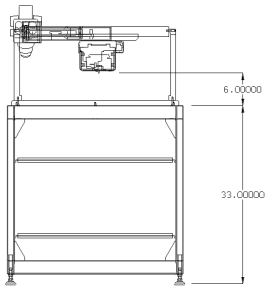
Dimensions
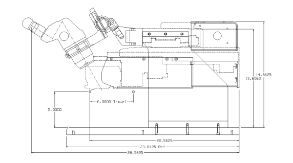
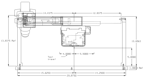
Machine dimensions are shown on the drawings below.
Weight is 410 lb. uncrated, or 450 lb. crated.
Side View
End View
Model No. 3500E-90

1551 S. Harris Court, Anaheim, CA 92806 Anaheim, CA 92806
Phone: 714.978.1551  Fax: 714.978.0431 Fax: 714.978.0431
Products | News | Events
| Support | Corporate | Contact Us | Universities | Home
Manual Die Bonders | Manual Wire Bonders | Semi-Automatic Wire Bonders | Automatic Wire Bonders | Pull Test Machines
|